Stilllegung des Forums
Das Forum wurde am 05.06.2023 nach über 20 Jahren stillgelegt (weitere Informationen und ein kleiner Rückblick).
Registrierungen, Anmeldungen und Postings sind nicht mehr möglich. Öffentliche Inhalte sind weiterhin zugänglich.
Das Team von spieleprogrammierer.de bedankt sich bei der Community für die vielen schönen Jahre.
Wenn du eine deutschsprachige Spieleentwickler-Community suchst, schau doch mal im Discord und auf ZFX vorbei!
Hey, ich implementiere aktuell einen Volume Renderer (Ray March) sowohl in Unreal als auch in Unity. Dazu verwende ich die Formel:
Quellcode
1
color= color * (1 - sampleValue) + sampleColor * sampleValue
Dabei ist color die Variable, die die Farbe aller Samples kumuliert. sampleValue ist der Wert an dieser Stelle in der 3D-Textur und sampleColor die Farbe dieses Voxels die über eine Transfertextur abhängig von dem sampleValue bestimmt wird.
Dieses Vorgehen ist teilweise selbst gebaut, da ich nur Quellen zu Beleuchtung etc. finde, wobei ich nur eine simple Farbkumulation haben will. Das funktioniert eigentlich auch gut, jedoch gibt es zwei Probleme:
1. Die Formel ist nicht unabhängig von der Anzahl an Abtastschritten. Mehr Schritte machen das Volumen dichter und heller, was auch irgendwie logisch ist, da mehr Datenpunkte pro Pixel abgetastet werden. Multipliziere ich den zweiten Summanden mit der Schrittgröße (... + sampleColor * sampleValue * stepSize) ist das Volumen schwarz, da die Farbe wohl zu stark abgeschwächt wird. Daher multipliziere ich den Summanden noch mit einem konstanten Faktor (64), was bei einer Schrittgröße von 1/64 das gewohnte Volumen liefert. Bei einer höheren Schrittzahl verblasst das Volumen jedoch, obwohl durch die kleinere Schrittgröße bei mehr Datenpunkten doch ungefähr die gleiche Helligkeit entstehen sollte. Umgekehrt ist bei sehr kleinen Schrittzahlen ein sehr helles Volumen zu erkennen (natürlich sehr formlos).
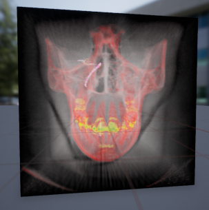
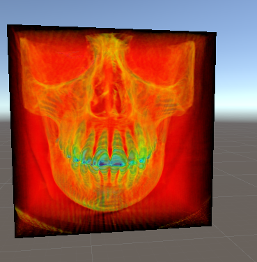
2. Trotz gleichem Algorithmus und gleicher Transfertextur komme ich bei den Engines auf unterschiedliche Resultate. Die Umgebung um den Schädel ist bei Unreal ein weißer Nebel und bei Unity rot, obwohl auch die gleichen Parameter verwendet werden. Ich habe keine Ahnung mit was das zu tun haben könnte. Ich verwende eine eindimensionale Regenbogentextur, die mit dem Sample-Wert als x-Koordinate abgetastet wird.
Code von Unity:
Shader "Custom/VolumeRenderer"
{
Properties
{
_VolumeTex ("Volume Texture", 3D) ="white" {}
_MaxSteps ("Max Steps", Int) =64
_Density ("Density", Float) =1.0
_TransferTex ("Transfer Texture", 2D) ="white" {}
}
SubShader
{
Tags { "Queue"="Transparent""RenderType"="Transparent""ForceNoShadowCasting"="True" }
Pass
{
Blend One One
CGPROGRAM
#pragma vertex vert
#pragma fragment frag
#include "UnityCG.cginc"struct appdata
{
float4 vertex : POSITION;
};
struct v2f
{
float4 vertex : SV_POSITION;
float4 localPos : TEXCOORD0;
};
sampler3D _VolumeTex;
sampler2D _TransferTex;
int _MaxSteps;
float _Density;
v2f vert (appdata v)
{
v2f o;
o.vertex = UnityObjectToClipPos(v.vertex);
o.localPos = v.vertex;
return o;
}
float2 lineBoxIntersection(float3 invRayDir, float3 localCamPos)
{
float3 isect0 = (0- localCamPos) * invRayDir;
float3 isect1 = (1- localCamPos) * invRayDir;
float3 closest = min(isect0, isect1);
float3 furthest = max(isect0, isect1);
float t0 = max(closest.x, max(closest.y, closest.z));
float t1 = min(furthest.x, min(furthest.y, furthest.z));
return float2(t0, t1);
}
fixed4 frag (v2f i) : SV_Target
{
// Preparation stage
float3 localCamPos = mul(unity_WorldToObject, float4(_WorldSpaceCameraPos, 1.00000000)).xyz;
float3 viewDir = normalize(i.localPos - localCamPos);
// transforms camera pos, so that in the box you have coordinate from [0;1] instead of [-0.5;0.5]// Assumes uniformly scaled box with pivot in the center and corresponding [-0.5;0.5] vertex coords
localCamPos = (localCamPos) +0.5;
// Precomputes reciprocal ray direction for line-box intersection
float3 invRayDir =1.0f / viewDir;
// Calculate intersections
float2 t = lineBoxIntersection(invRayDir, localCamPos);
// Aligning first sample point to view planes to remove moire-aliasing//float planeOffset = 1 - frac((t.x - length(localCamPos - 0.5)) * _MaxSteps);//t.x += (planeOffset / _MaxSteps);//t.x = max(0, t.x);
float3 entryPos = localCamPos + (max(0, t.x) * viewDir);
// Calculate thickness of the box, i.e. 1.0 iff the ray goes parallel to one side and can go // up to sqrt(2) for a ray from one corner diagonal to the opposite// We need this, so that we know how many steps we have to takefloat boxThickness = max(0, t.y - t.x);
// We keep the original step sizefloat stepSize =1.0/ _MaxSteps;
float actualStepCount = floor(boxThickness * _MaxSteps);
actualStepCount = clamp(actualStepCount, 0, 512);
// Actual ray marching// Perform back-to-front ray-marching
float3 endPos = entryPos + viewDir * actualStepCount * stepSize;
float3 color = float3(0,0,0);
for(int i =0; i < actualStepCount; i++)
{
float sampleValue = tex3Dlod(_VolumeTex, float4(endPos,0.f)).a;
float4 transferColor = tex2Dlod(_TransferTex, float4(sampleValue, 0.0f, 0.0f, 0.0f));
sampleValue *= transferColor.a;
color = color * (1.0f - sampleValue) + transferColor.rgb * sampleValue * stepSize *64;
endPos -= viewDir * stepSize;
}
// exponential density function//float finalColor = 1 - exp(-accumdist * _Density);return fixed4(color, 1);
}
ENDCG
}
}
}
Hier nur der Ray-Marcher-Teil von Unreal, da die Vorberechnungen gleich sind und den Material-Graph involvieren. Das Material verwendet Additives Blending (hier zur besseren Darstellung Opak d.h. schwarzer Hintergrund) und berechnet die Farbe die als Emissive Color verwendet wird.
Ist schon ein deutlicher Unterschied. Gleiche Schrittzahl, gleicher Algorithmus, gleiche Texturen. Mir sind die Feinheiten der Rendering-Pipelines nicht bekannt, und ich kann daher nicht einschätzen ob es da wichtige Unterschiede gibt. Ich hoffe daher hier auf Hilfe.

